Solution proposal - exercise 10
Task 1
Task 2
Task 3
Task 4
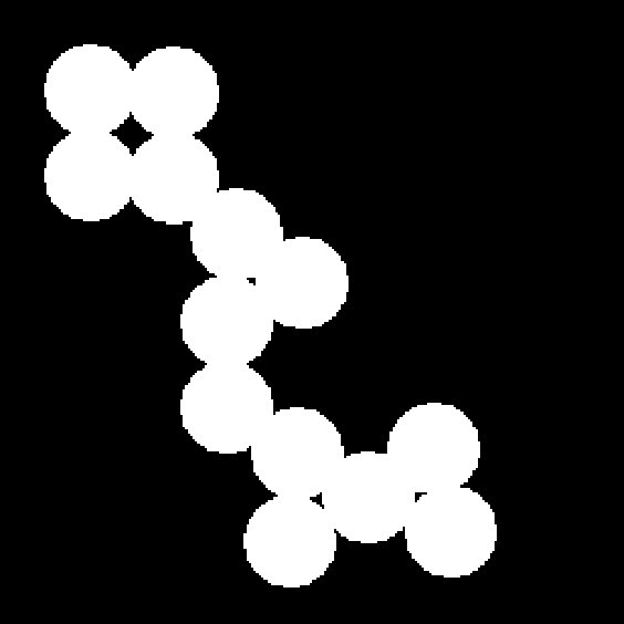
a)
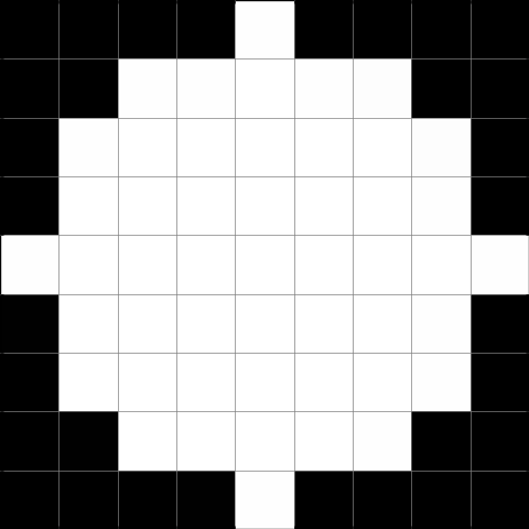
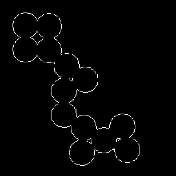
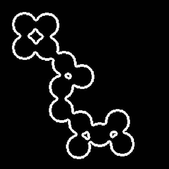
Here, we perform edge detection with two different sizes disks as structuring elements.

b)
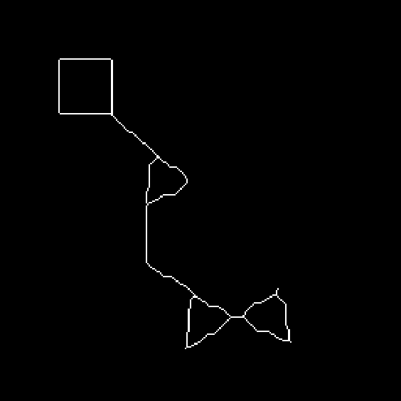
c)
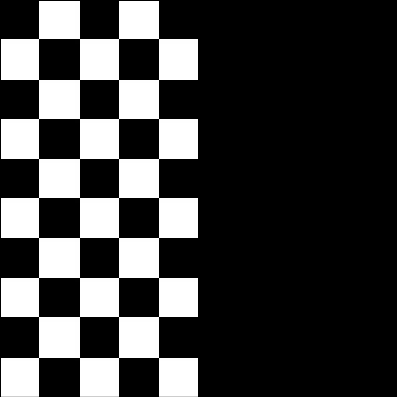
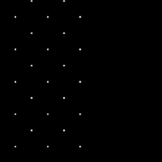
First, we try with a hit-or-miss with structure elements
and the results can be seen in Figure 4.5.
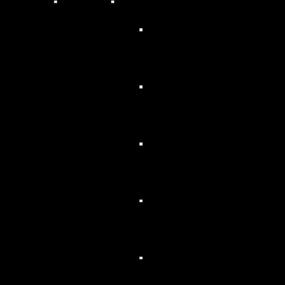
If we in stead employ the following structuring elements
we get the location the top right corner of all white squares, as shown in Figure 4.6.
Task 5
The original image is shown in Figure 5.1.

First, we fill the holes of the image.

Then, we subtract the original image from the filled one to obtain the holes.
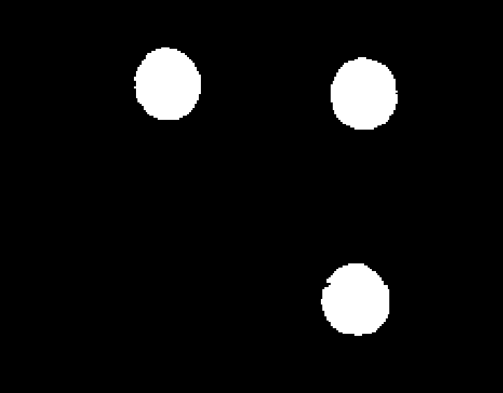
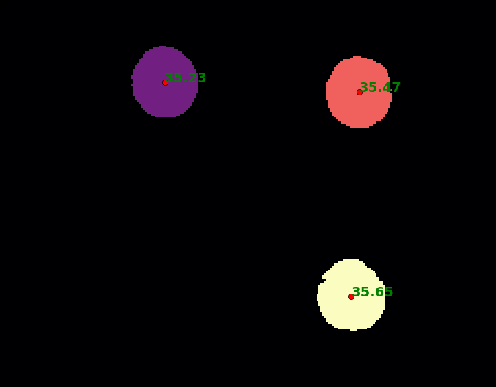
Using the fact that they are almost circular, we can compute the the diameter from the perimeter and the location of the center points. The result is shown in Figure 5.4.
Task 6
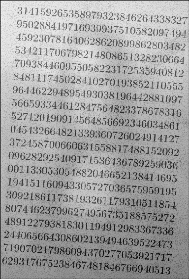
Original image showing the start of the decimal progression of superimposed over a version of the Mona Lisa painting. The task is to isolate the numbers in the image.
Trying with a simple, global thresholding works poorly.
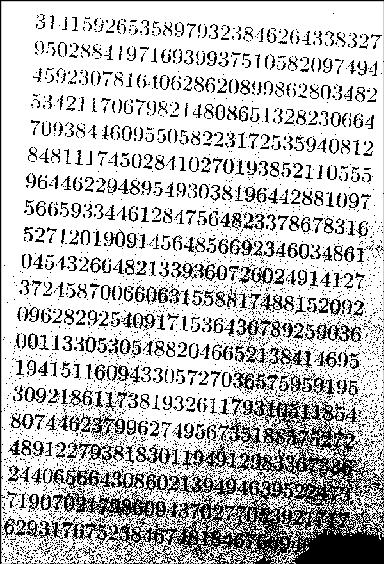
We clearly need another approach. We will try to separate the numbers and the Mona Lisa background, and we do it by first extracting the background with morphological closing
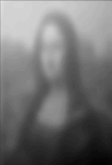
and subtract the original from this background image.
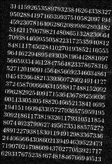
This is exactly (per definition) the same as performing a bottom-hat (or black top-hat) transformation on the original image, which can be seen by comparing Figure 6.4. and Figure 6.5.
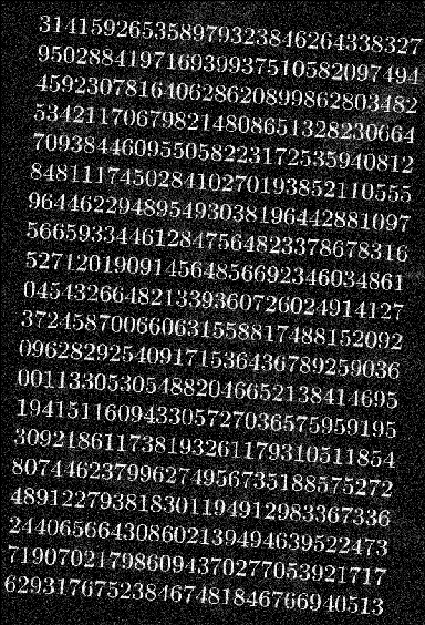
Employing a global thresholding on this image is more successful.
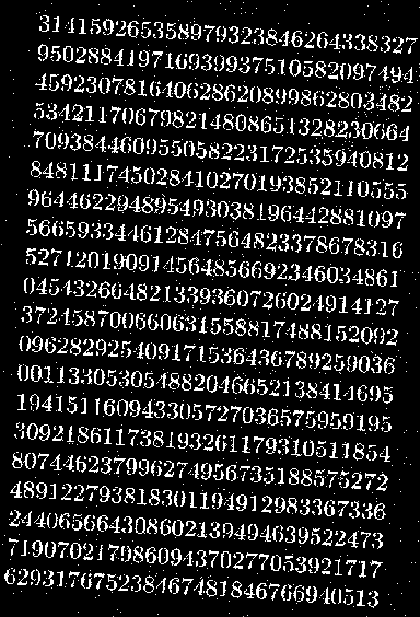
We can clean the result by removing the pixel dust (salt noise).
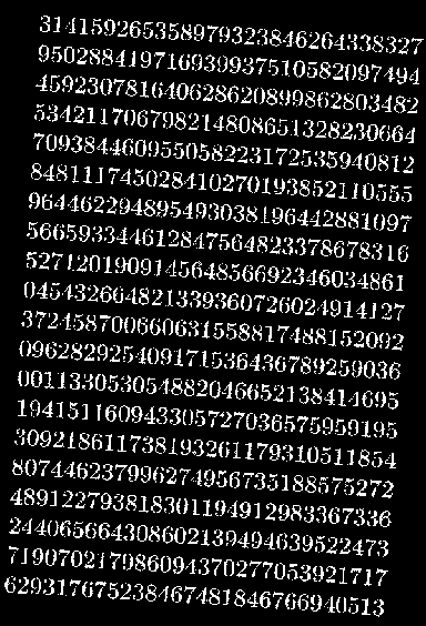
Finally, we invert the colors.
