Solution proposal - exercise 5
Task 1
Step 1
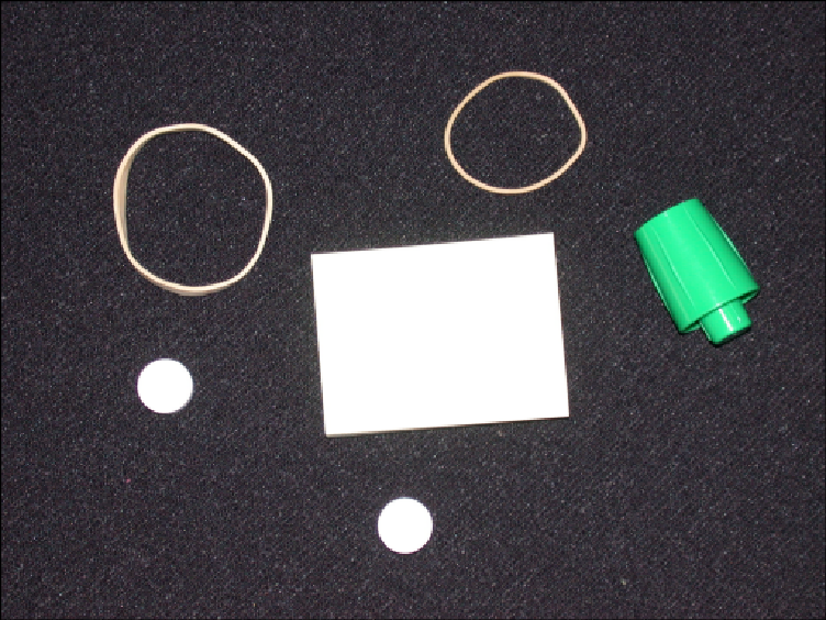
Step 2
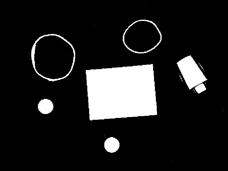
Step 3
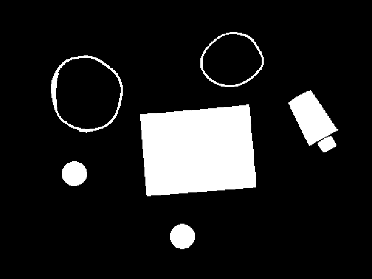
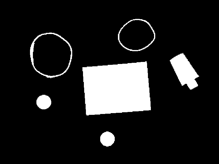
Step 4

Step 5
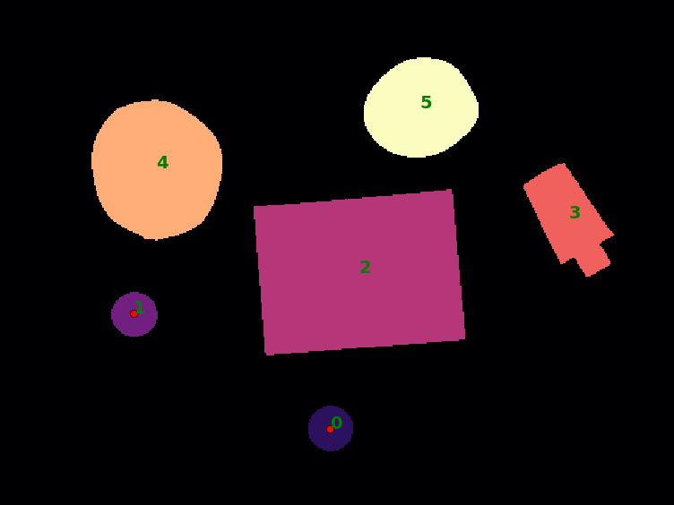
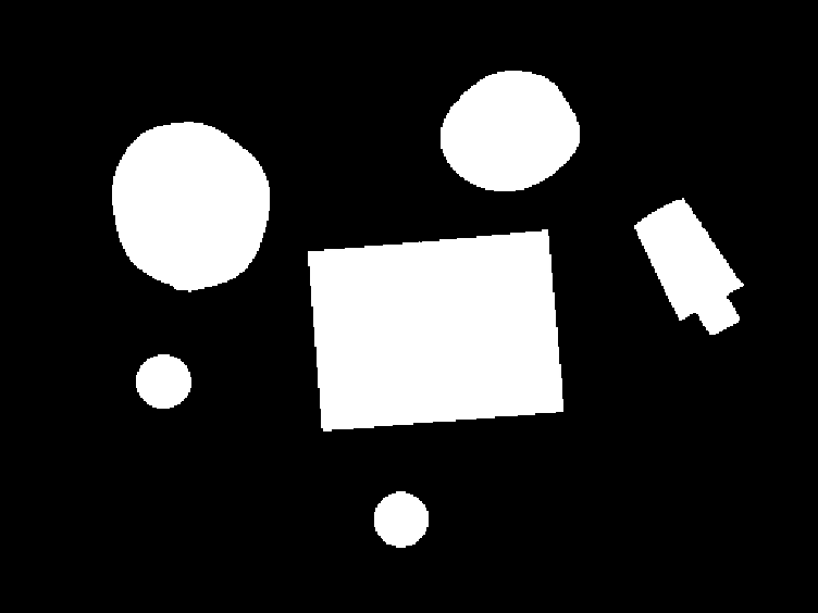
Object properties
| Object | Area | Perimeter | Roundness |
|---|---|---|---|
| 0 | 882 | 110.57 | 0.907 |
| 1 | 876 | 110.57 | 0.900 |
| 2 | 16,928 | 543.05 | 0.721 |
| 3 | 3,026 | 261.12 | 0.558 |
| 4 | 8,074 | 338.88 | 0.884 |
| 5 | 4,908 | 264.01 | 0.885 |
Task 2
Step 1
Step 2

Step 3
Step 4
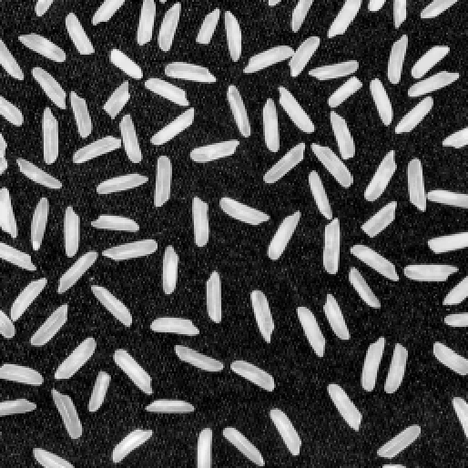
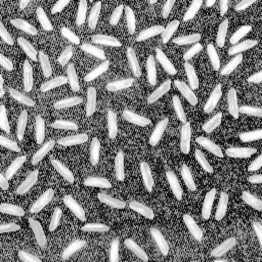
While the histogram equalization indeed increased the contrast, it enhanced the contrast in the background to much for it to be useful. Admittedly, a better contrast enhancer should have been used.

Step 5
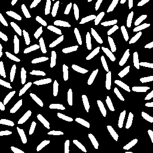
Because of the contrast adjustment failure discussed in Step 4, we threshold the foreground image directly.
Step 7

Step 8

Step 11
Step 12
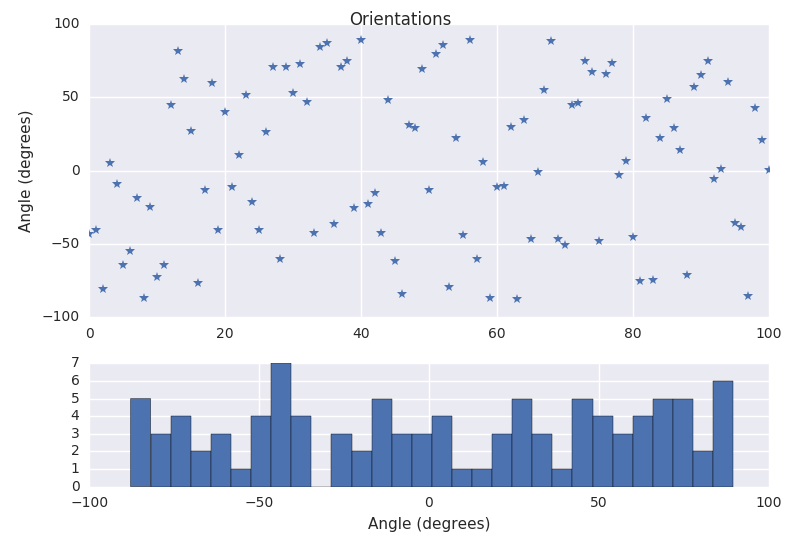
Step 13
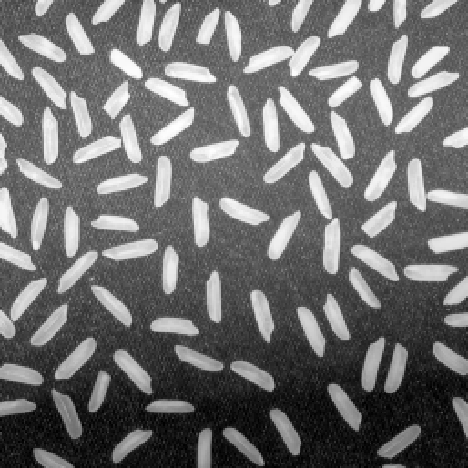
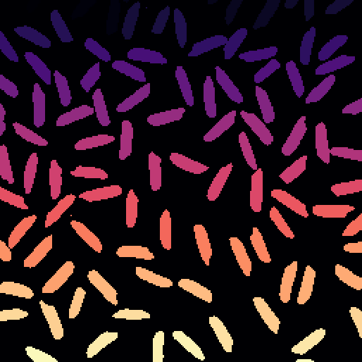
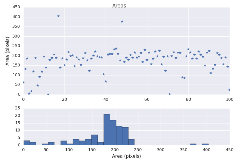
Here we plot the annoted image. Note that some objects like number 18 and 49 are the result of not being able to separate some of the grains.

Task 3
We where suppose to estimate the area and perimeter of the difference circles shown in Figure 3.1, Figure 3.2, and Figure 3.3.
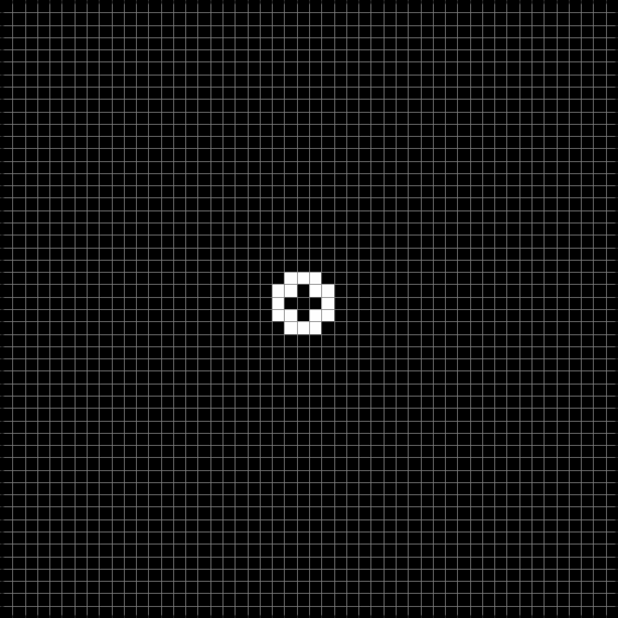
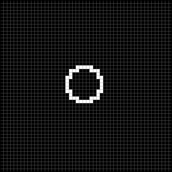
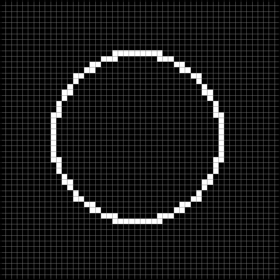
The results that are as follows, note that the perimeter and area computed from the radius is a difficult standard to live up to as these objects are not continuous. Also, note that the boult in routines from OpenCV seems to be using Freeman chain code to estimate the perimeter and area from the contour points.
| Perimeter | circle2 | circle5 | circle15 |
|---|---|---|---|
| From radius | 12.57 | 31.42 | 94.25 |
| CC Freeman | 13.66 | 35.31 | 101.25 |
| CC Kulpa | 12.95 | 33.48 | 96.00 |
| CC Vossepoel | 12.83 | 33.04 | 95.23 |
| Contour naive | 15.00 | 39.00 | 119.00 |
| Contour OpenCV | 13.66 | 35.31 | 101.25 |
| BQPM 4-connected | 20.00 | 44.00 | 124.00 |
| BQPM Duda | 16.49 | 38.14 | 104.08 |
| BQPM Gray | 20.00 | 44.00 | 124.00 |
| Area | circle2 | circle5 | circle15 |
|---|---|---|---|
| From radius | 12.57 | 78.54 | 706.86 |
| CC Freeman | 14.00 | 84.00 | 716.00 |
| Contour OpenCV | 14.00 | 84.00 | 716.00 |
| BQPM 4-connected | 21.00 | 101.00 | 761.00 |
| BQPM Duda | 21.50 | 102.00 | 765.00 |
| BQPM Gray | 21.00 | 101.00 | 761.00 |
Task 4
a)
The moments of inertia of an image (around a point is simply the second order moment around said point (referring to the notes for reference).
b)
For a 2D object to exhibit a unique orientation, the requirement is simply , where denotes the central moments.
c)
For the first one
And for the second